Scale Drawing Dual Axis ( Drawing Editor & Modeling )
Tool summary :
- Scales PDF or other drawings for use as reference drawings in Modeling . The tool is available in Modeling and the Drawing Editor .
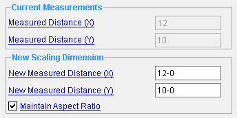
The Adjust Drawing Scale window opens after you locate points to set the " Measured distance (X) " and " Measured distance (Y) " that is shown in this window. " Okay " " Cancel "
Also see :
- Modeling (where Scale Drawing Double Axis is a reference drawing tool)
- Drawing Editor (where Scale Drawing Dual Axis is a tool)
- Set Reference Point (sets the point about which the drawing is scaled)
- Move (a drawing location tool in Modeling )
page 1 | contents | reference drawing tools (modeling) | tools > (drawing editor) | top
Drawing Scaling Example :
Before using this tool in Modeling :
Optional : Verify that the reference point for the drawing that you want to scale is in the desired location
Before using this tool in the Drawing Editor :
Recommended : Unshorten if you are in a shortened reference drawing.
|
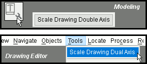
1 . In Modeling , invoke Scale Drawing Double Axis . In the Drawing Editor , invoke Scale Drawing Dual Axis . |
|
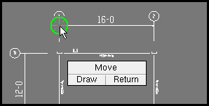
2 . Left-click ( Draw ) to select the first point on the X-axis that you want to locate -- in this case, one end of a horizontal dimension associated with the reference drawing. |
|
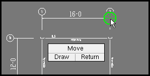
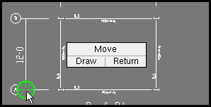
3 . Left-click ( Draw ) to select the second point on the X-axis that you want to locate -- in this case, the opposite end of the horizontal dimension that you selected in step 2.
|
|
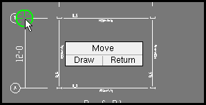
4 . Left-click ( Draw ) to select the first point on the Y-axis that you want to locate -- in this case, one end of a vertical dimension associated with the reference drawing. |
|
5 . Left-click ( Draw ) to select the second point on the Y-axis that you want to locate -- in this case, the opposite end of the vertical dimension that you selected in step 4.
|
|
6 . Check " |
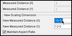
Tip: To resize the reference drawing to an exact scale, select points whose distance apart in the original drawing along the X- and Y-axis is known. In the example above, you select the ends of horizontal and vertical dimensions. That way, when you enter the " New Measured Distance (X) ," you can enter ' 16-0 ' to rescale the drawing to full size along it's X-axis, and enter ' 12-0 ' to the " New Measured Distance (Y) " to rescale the drawing to full size along it's Y-axis.
page 1 | contents | reference drawing tools (modeling) | tools > (drawing editor) | top
Step-by-step instructions (also see the example ) :
To accurately enter distances on a reference drawing that has been shortened, you may have to first Unshorten . The following instructions assume that you are using a 3-button mouse.
1 (optional) . Before using this tool in Modeling :
Verify that the reference point for the drawing that you want to scale is in the desired location, because the drawing will be scaled in reference to that insertion point . You can do this in Modeling by clicking the " Set Reference Point " button on the Reference Drawing Tools window, or in the Drawing Editor by doing a Verify Reference Point . You can, however, set the reference point later, as well as press the " Move " button to relocate the drawing.
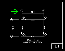
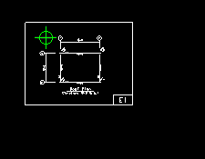
Before : The drawing is linked, and added to the drawing without being scaled.
After : The drawing is scaled, but the reference point (shown green here) remains in the same location in the model.
2 . Invoke Scale Drawing Double Axis using any one (1) of the following methods:
Drawing Editor : Click the Scale Drawing Dual Axis icon. The icon can be taken from the group named ' Tools '. and placed on a toolbar (classic) or the ribbon (lightning).
Modeling : Click the Reference Drawing Tools icon. The icon can be taken from the group named ' Model '. Highlight the desired drawing in the list, then press the Scale Drawing Double Axis button.
Drawing Editor & Modeling : Scale Drawing Single Axis ( Drawing Editor ) or Reference Drawing Tools (Modeling) can also be configured to be invoked using a keyboard shortcut , the context menu , or a mode . For the lightning interface, this configuration is done using Customize Interface .
3 . Draw - Move - Return mouse bindings become active along with various Locate options. The status line prompts you to " Select first point for x axis ."
|
|
|
bindings |
3a (optional) : Select the Locate icon that you want (if it's not selected already).
3b : Place the mouse pointer (
) so that the point location target (
) snaps to the first point on the X-axis that you want to locate, then left-click ( Draw ).
Note: It doesn't matter whether you select the leftmost or rightmost X-axis point first -- the " Measured Distance (X) " will always be positive.
4 . Draw - Move - Return mouse bindings continue to be active. The status line prompts you to " Select second point for x axis ."
|
|
|
bindings |
4a (optional) : Select the Locate icon that you want (if it's not selected already).
4b : Place the mouse pointer (
) so that the point location target (
) snaps to the second point on the X-axis that you want to locate, then left-click ( Draw ).
Note: It doesn't matter whether the point you enter is exactly parallel to the X-axis -- only the horizontal distance between the two points along the X-axis is entered as the " Measured Distance (X) ."
5 . The status line prompts you to " Select first point for y axis ."
|
|
|
bindings |
5a (optional) : Select the Locate icon that you want (if it's not selected already).
5b : Place the mouse pointer (
) so that the point location target (
) snaps to the first point on the Y-axis that you want to locate, then left-click ( Draw ).
Note: It doesn't matter whether you select the topmost or bottommost Y-axis point first -- the " Measured Distance (Y) " will always be positive.
6 . The status line prompts you to " Select second point for y axis ."
|
|
|
bindings |
6a (optional) : Select the Locate icon that you want (if it's not selected already).
6b : Place the mouse pointer (
) so that the point location target (
) snaps to the second point on the X-axis that you want to locate, then left-click ( Draw ).
Note: It doesn't matter whether the point you enter is exactly parallel to the Y-axis -- only the vertical distance between the two points along the Y-axis is entered as the " Measured Distance (Y) ."
7 . The Adjust Drawing Scale window opens. The Scale Drawing Double Axis tool reports absolute value of the difference between the X coordinates of the points located in steps 3 and 4 and reports that distance (in the primary dimension " Units ") on the " Measured Distance (X) " field of the Distance Ruler window. Similarly, it reports the difference between the Y coordinates of the points located in steps 5 and 6 on the " Measured Distance (Y) " field.
7a (optional) : Adjust the " New Measured Distance (X) " to rescale the drawing, so that any part of the drawing that was previously the meaured distance along its X-axis is scaled to the distance you enter.
7b (optional) : Adjust the " New Measured Distance (Y) " to rescale the drawing, so that any part of the drawing that was previously the meaured distance along its Y-axis is scaled to the distance you enter.
Alternative : If the drawing is proportional before you scale it -- that is, if a unit of measurement in the X-axis already equals a unit in the Y-axis in the drawing -- you may check "
Maintain Aspect Ratio " to "lock" the two fields together so that the X- and Y-axis values remain proportional. When checked, if you make an entry to a " New Measured Distance... " field, the other " New Measured Distance... " field is updated automatically.
Note: If you skip both steps (7a and 7b), the drawing will not be scaled.
8 . To close the Adjust Drawing Scale window, press " OK " or " Cancel ."
"OK" (or the Enter key) closes this window and scales the drawing about its reference point, if you adjusted the " New Measured Distance (X) " or " ...(Y) " fields in step 7.
"Cancel" (or the Esc key) closes this window without scaling the drawing.
Note: In Modeling , you can " Move " the reference drawing to better coordinate the drawing with the 3D model.
page 1 | contents | reference drawing tools (modeling) | tools > (drawing editor) | top
------ Current Measurements ------
Measured Distance (X): This read-only information field reports the absolute value of the difference between the X coordinates of the points that you enter when you are prompted to select point for the X-axis. The global coordinate system is used to calculate the distance (in the primary dimension " Units " or other units ) between the points.
Measured Distance (Y): This read-only information field reports the absolute value of the difference between the Y coordinates of the points that you enter when you are prompted to select point for the Y-axis. The global coordinate system is used to calculate the distance (in the primary dimension " Units " or other units ) between the points.
------ New Scaling Dimension ------
New Measured Distance (X): The distance (in the primary dimension " Units " or other units ) to which the " Measured Distance (X) " will be scaled along the X-axis of the global coordinate system when you press " OK ."
New Measured Distance (Y): The distance (in the primary dimension " Units " or other units ) to which the " Measured Distance (Y) " will be scaled along the Y-axis of the global coordinate system when you press " OK ."
Maintain Aspect Ratio: ![]() or
or ![]() . This ensures that the drawing remains proportional when you make entries to the " New Measured Distance (X) " and " New Measured Distance (Y) " fields.
. This ensures that the drawing remains proportional when you make entries to the " New Measured Distance (X) " and " New Measured Distance (Y) " fields.
If this box is checked (
), when you enter a new value into a " New Measured Distance... " field, the other " New Measured Distance... " field is updated automatically, so that their X- and Y-axis values remain proportional.
If this box is not checked (
), when you enter a new value into a " New Measured Distance... " field, the other " New Measured Distance... " field is not automatically updated.
page 1 | contents | reference drawing tools (modeling) | tools > (drawing editor) | top
Bottom-row buttons :
"OK" (or the Enter key) closes this window. It also scales the drawing if entries were made to the " New Measured Distance... " field s.
"Cancel" (or the Esc key) closes this window without changing scaling the drawing.
page 1 | contents | reference drawing tools (modeling) | tools > (drawing editor) | top


